Table of Contents
Introduction
In previous posts of this series, (Part-1, Part-2), we have seen several representations of the association construct. In this article we continue our investigation with the Graph Data model. Despite its mere representation as nodes and edges, the structure of this model and its implementation details varies a lot in Graph Databases. There is still a strong controversy and perhaps confusion on what makes a database, a Graph database and many are not fully aware that there exist other types of Graph Databases apart from Property Graph Database. Things get more complicated because the engine of a Property Graph Database is not the same kind of engine with either an RDF store or engines based on Topic Maps or Relational data model. Property Graph data model is neither close to Object Model, a data model that is found in Object-oriented database management systems. There are significant differences of the Property Graph data model at both the logical and the physical level with all other models and it has not been established yet as a standard. Which brings us to the question whether there is indeed a necessity for another data model standard based on the association construct to fill the space of Property Graph databases and bridge also the gap with other Semantic Web technologies, especially JSON for Linking Data. This question will not be answered in this post, we will make an attempt instead to give a formal definition of the association construct using the mighty Wolfram Language and compare it with RDF and Property Graph components and this will prepare also the ground for introducing our R3DM data model later on.
Wolfram Language EntityPropertyAssociation
Real-world entities are another kind of symbolic expression that exists in latest versions of the Wolfram Language. You can get the values of specific properties for an Entity, if it exists in Wolfram Knowledgebase, world’s largest and broadest repository of computable information according to Wolfram. But you do not write a query to fetch the data, you use a functional approach instead. The network delay for a first time search on specific values of EntityProperties is minimal. For example:
Socrates=Entity["Person","Socrates::dnz7w"];
EntityValue[
  {Socrates},
  {gender,date of birth,place of birth,parents,children},
  "EntityPropertyAssociation"]
Notice the third argument of the EntityValue function here, EntityPropertyAssociation will format the output, Fig. 1, of this calculation as an association in which the specified entity is the key, and value is another nested association of properties and EntityProperties values.
Wolfram Language EntityPropertyAssociation
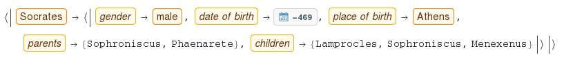
A boxed word is the symbolic Wolfram Language Knowledge Representation of a named entity of any type, (e.g. Person, City, Property), that is used as a handler to access records of information about that Entity that are stored in Wolfram Knowledgebase. The reader should realize how important this symbolic representation is in data modeling. Although the developer/user may compute a solution with a boxed CommonName, e.g. Socrates, behind the scenes a canonical name, e.g. Socrates::dnz7w, is used as the unique identifier for the Entity to disambiguate and to interpret user’s instructions.
This EntityPropertyAssociation representation extends Wolfram Language fundamental Association construct, and it is in accordance with Topic Map Association serialization that we discussed in the second part of our series. The following figure, Fig. 2, is from a previous example that is included in Part 1 of our series and depicts three associations of this kind in a Wolfram Dataset. Each association represents an Entity type instance ($PartI, $SupplierJ and $CatalogK) and for each instance the entity type ($Item, $Organization, $Inventory) is embedded as a key value pair together with other EntityProperties key-value pairs.
Three Associations in a Named-Row Dataset
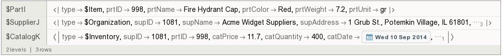
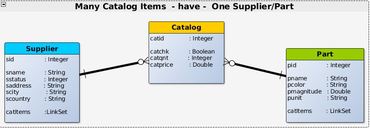
Contrast this with mere tuples from the three tables of our relational database, Supplier, Part, Catalog. Semantically speaking, the three tuples cannot stand alone without the header of the relation body and their relation type. In addition to that observation, each value of either an EntityPropertyAssociation or member of a tuple, is always dependent on their sibling nodes. Therefore values cannot be handled in isolation.
{ {998, "Fire Hydrant Cap", "Red", 7.2, "gr"},
  {1081, "Acme Widget Suppliers", "1 Grub St., Potemkin Village, IL 61801", "ILLINOIS", "USA", 10},
  {1081, 998, 11.7, 400, "2014-9-10", True} }
R3DM Hypergraph Terminology
A Hyperbond hyperlinked to HyperAtoms

The figure on the left, Fig. 3, illustrates a single EntityPropertyAssociation of Part no. 998 with its properties and values. According to Hypergraph theory, red nodes are hypernodes and the green node is the hyperedge where here connects a set of hypernodes. In R3DM we use the following definitions and terminology.
An EntityPropertyAssociation can be defined as an Association of entity’s attributes (properties) with values. Each attribute-value pair is represented on the hypergraph by a hyperatom. Therefore the general form of a hyperatom is a key-value pair. Each hyperatom is always connected bidirectionally to a hyperbond with a hyperlink. Normally hyperlinks do not have labels or direction. A hyperbond represents a complex structure, such as a tuple of a relation or instance of a class. The role of a hyperbond is to connect a set of hyperatoms. A hyperbond to hyperbond connection is also possible.
Two important observations:
-
You can easily spot similarities between R3DM hypergraph paradigm and JSON documents. A JSON object can be represented with a
hyperbondand a field-value pair (property) can be represented with ahyperatom. -
Entities, attributes (variables), and values each has its own type system in R3DM. These type systems will be analyzed methodically in another post but you can get a taste of what they look like here.
Property Graph
We defined EntityPropertyAssociation and we got familiar with the terminology of R3DM hypergraph. We can now proceed to examine the analogy with the Property Graph data model.
Recall that a property graph has vertices and edges where :
-
each vertex has
- a set of outgoing edges.
- a set of incoming edges.
-
each edge has
- an outgoing tail vertex.
- an incoming head vertex.
- a label that denotes the type of relationship between its two vertices.
-
vertex and edge have
- a unique identifier
- a collection of properties defined by a map from key to value.
We built a property graph data model for our Supplier-Part-Catalog example in OrientDB, a very popular, open-source, and free multi-model database.
Property Graph Nodes
OrientDB allows both schema-full and schema-less creation of classes. Each class represents either a type of nodes or a type of edges on the graph. In the manner of a relational schema, we can add properties of a class with OrientDB SQL commands.
CREATE CLASS Part EXTENDS V;
CREATE PROPERTY Part.pid INTEGER;
CREATE PROPERTY Part.pname STRING;
CREATE PROPERTY Part.pcolor STRING;
CREATE PROPERTY Part.pweight DOUBLE;
CREATE PROPERTY Part.punit STRING;
ALTER CLASS Part SHORTNAME P;
Then we can populate the class with records, e.g. create a vertex (an instance of type Part) that represents Part no. 998 (Red Fire Hydrant Cap)
CREATE VERTEX Part CONTENT
{"pid":998,"pname":"Fire Hydrant Cap","pcolor":"Red","pweight":7.2,"punit":"lb"}
Property Graph with Directed Edges
Now comes the tricky part, we want to associate Suppliers with Parts. Notice that in Property Graph data model there is not an associative entity to resolve a many-to-many relationship. We only have the concept of a directed edge that links one vertex with another vertex. Let us define the type of edge first.
CREATE CLASS inCatalog EXTENDS E;
CREATE PROPERTY inCatalog.catsid INTEGER;
CREATE PROPERTY inCatalog.catpid INTEGER;
CREATE PROPERTY inCatalog.catprice DOUBLE;
CREATE PROPERTY inCatalog.catqnt INTEGER;
CREATE PROPERTY inCatalog.catdate DATETIME;
CREATE PROPERTY inCatalog.catchk BOOLEAN;
ALTER CLASS inCatalog SHORTNAME C;
In this OrientDB DDL inCatalog.catsid and inCatalog.catpid are superfluous, we added them for comparison purposes with the relational model. Records of edge type inCatalog contain record identifiers for the outgoing tail vertex and the incoming head vertex Fig. 11. Secondly, it is not specified in the schema that this type of edge, inCatalog, connects Suppliers with Parts, neither is specified any direction on how to link these two types. These are defined during the creation of an edge.
One way of creating inCatalog instances is to read each Catalog record from the table, get OrientDB record identifiers (RIDs) for the specific Supplier and Part and then execute OrientDB CREATE EDGE SQL command to create a bidirectional edge. For example:
CREATE EDGE inCatalog FROM #19:0 TO #18:7 CONTENT
 {"catsid":1081,"catpid":998,"catprice":11.7,"catqnt":400,"catdate":"2014-09-10","catchk":true}
Newcomers can easily get confused with Property Graph edges. This is because although the outgoing tail and the incoming head of the edge implies a directed graph, in practice we can traverse the graph bidirectionally, i.e. start from any node to reach another node independent of the direction of the edge.
A Many to Many Relationship on a Property Graph
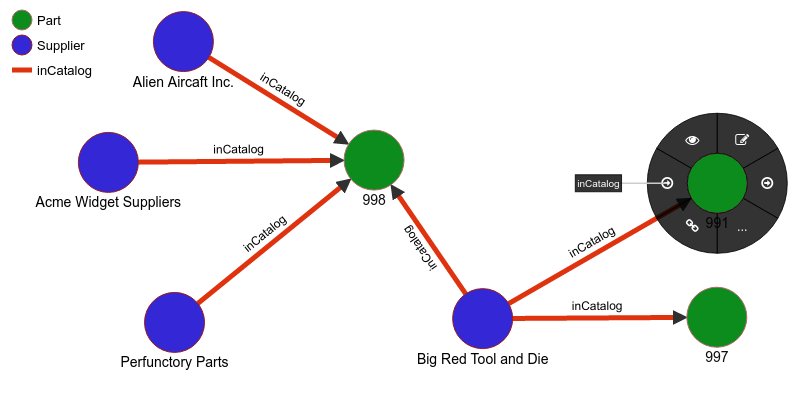
In this screen capture, Fig. 4, of OrientDB graph canvas one Supplier is associated with three Parts and one Part is associated with three Suppliers. We observe that inCatalog edges are always from a Supplier to a Part. This is because we created edges this way, we could have created them equally in the opposite direction. Semantically speaking, both Supplier and Part participate in a Catalog association and their binary relation is not directed. In such a case Property Graph edges look like Topic Map binary associations. The label of the edge is the type and the roles of its members are played by the outgoing head (out) and incoming tail (in), Fig. 5.
Directed Bidirectional Edge

Property Graph with Bidirectional Links
Hence the bidirectional nature of the edge can be seen in two ways.
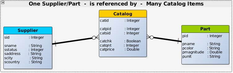
Firstly the out and in links can be considered as one-to-one relationship of an edge with vertices. One Supplier/Part is referenced by Many Catalog items. The fields that are linked are the RID of Catalog with the RID of Part or Supplier, Fig. 11. This type of direct linking is similar to the many-to-many relationship with a join-table, Fig. 6.
Many-to-Many relationship with direct links on Associative Entity (edge)
Secondly, on the one side of the relationship, i.e. on the vertex we have the link set of outgoing/incoming edges, Fig. 8 and Fig. 9. For example, many Catalog items (LinkSet) have One Supplier/Part, Fig. 7.
Many-to-Many relationship with sets of direct links
The following query returns a list of both the outgoing edges for Big Red Tool and Die Supplier, see Fig. 4, and the list of associated Parts, Fig. 8.
select @rid As Supplier,
       out_inCatalog as Catalog, out() As Part,
       sid As supplierID, out().pid As partID,
       scountry, scity
from 19:1
Set of Outgoing Edges for Supplier

In a similar fashion, we can ask for the list of incoming edges to Part no. 998, see Fig. 4, and the list of Suppliers that provide that Part, Fig. 9
select @rid As Part,
       in_inCatalog as Catalog, in() As Supplier,
       pid As partID, in().sid As supplierID,
       pname, pcolor
from 18:7
Set of Incoming Edges for Part

The set of outgoing edges from the Supplier and the set of incoming edges to Part no. 998 have a common edge, 17:11, that connects this Supplier with this Part, see Fig. 4.
Property Graph and Object-Oriented database
We could have implemented bidirectional edges on top of OrientDB Document data model using Link, Link list, Link set data structures and the CREATE LINK SQL command. If you take also into account its class inheritance, schema-full, and SQL methods features, that brings us pretty close to the object-oriented database model. Objects, in turn, may reference one another and therefore form a network graph. A relationship, in particular, is an association between two persistent objects, each of a specific type. In Intersystems Cache, relationships are binary, i.e. defined between two classes and bidirectional, i.e. both sides of a relationship must be defined by creating a pair of complementary relationship properties, one in each class. Two-way reference property in both classes, collection in “one” side and simple reference in “many” side are analogous to the link set of outgoing/incoming edges in a vertex and the out/in links in edge of Property Graph data model, Fig. 8, Fig. 9, Fig. 11.
Association vs Edge
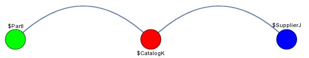
If we take these “Three Associations in a Named-Row Dataset”, Fig. 2, and create a graph with analogy to the Property Graph data model, we can see that $PartI (green node), $CatalogK (red edge), and $SupplierJ (blue node) are hyperbonds, i.e. they are EntityProperty associations and they are connected with hyperlinks i.e. undirected bidirectional links, [Fig. 10].
Three Hyperbonds connected with Hyperlinks
There are three main advantages using R3DM hypergraph instead of a Property Graph:
-
There is a uniform treatment of records for both entities (nodes) and associative entities (edges). In R3DM these are symbolically represented by
hyperbonds. Hyperlinkinghyperatomsorhyperbondsis not the same as connecting property nodes with property edges. -
Entities, attributes and values are completely separable. There is not an Entity-Attribute neither an Entity-Attribute-Value ‘Silo’ structure. This will become clear at a later post on the associative characteristics of R3DM. Here it is enough to say that the collection of properties defined by a map from key to value are enclosed in the structure of property graph node/edge. On the contrary in data models such as RDF, Topic Map and our R3DM hypergraph each key-value pair (
hyperatom) can be a single instance and the same value can be linked to more than one classes (hyperbonds) or instances of the same class, see the discussion here -
Under the hood, in a Property Graph each regular edge between two nodes creates another record. You cannot link one node record directly to another node record, you must always cross the edge record either from its tail or from the head. But with a
hyperlinkthings are different, you do not need to load any edge record to resolve the other part of the relationship, no edge document is created. Thankfully, OrientDB provides such a data structure, it is the Lightweight Edge. We have implemented R3DM in OrientDB using Lightweight Edges and it will be fully described in an upcoming post.
Join vs Edge
Now, examine this relational database sql query here with the following comparable OrientDB Property Graph query:
/* Suppliers of a Red Fire Hydrant Cap sorted by their Catalog price */

select out as supRID,
       out.sname as supName,
       out.scountry as supCountry,
       catprice as catPrice,
       catqnt as catQuantity,
       in as prtRID,
       in.pname as prtName,
       in.pcolor as prtColor,
       @rid as catRID
from inCatalog
where in.pid=998
order by catPrice
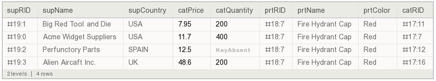
Suppliers of a Red Fire Hydrant Cap
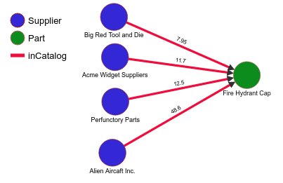
Suppliers of a Red Fire Hydrant Cap on OrientDB Graph Canvas
This OrientDB SQL query is clearly more compact and with a faster performance, because there are no JOIN operations anymore. We can get back the result set represented with a Wolfram Dataset structure, Fig. 11. Instead of having supplier IDs and part IDs, these are now replaced with OrientDB record IDs (RIDs). We have also added another column at the end which is the RID of the edge record, i.e. Catalog record.
Check also this Topic Map graph representation. The main difference is that these Catalog relationships and the Part tuple are drawn explicitly on the Topic Map and all values of properties are visible on the same graph. In this Property Graph, Fig. 12, only one of the enclosed properties of any node or edge type is displayed.
Summary
We can summarize the critical points of our investigation in Property Graph data model:
- We introduced R3DM Hypergraph as the harbinger of R3DM associations. R3DM hypergraph is based on Wolfram
EntityPropertyAssociationsand extends Property Graph withhyperbondsthat represent in a uniform waynodesandedges; whilehyperatomsarehyperlinkedtohyperbondsand are analogous to a property-value pair. From this perspective:
- There is not an Entity-Attribute or Entity-Attribute-Value ‘Silo’ structure.
- Hypelink, i.e. bidirectional edge without a record, can link directly
hyperatomstohyperbondsandhyperbondtohyperbond
-
In all the data models we have described so far in our series, every value is accessible only by knowing its context. Thus far, values are either dependent on a relation variable and attribute in a Relational model, or they come as field-value pairs in the object of a Document model / Object-Oriented model, or you have Topic Type and Topic Roles in Associations of Topic Map model, or they form property-value pairs that are enclosed in the node structure of Property Graph model. Even in the triplets of RDF model, that we will examine in the next article, you have an entity-property-value context.
-
Generally speaking, in Property Graph data model schema specifications for Node and Edge types are weak and it is not easy to define referential integrity and handling of many-to-many relationships. OrientDB object-oriented features alleviate that problem.
-
In a Property Graph data model edges are always directed but we can traverse them in both ways, i.e. they link bidirectionally nodes of the graph. In this sense, the label of the edge is comparable to the Topic type of a binary association in Topic Map data model; whereas, the labels
outandinthat signify the outgoing head and incoming tail are the roles of its members. -
In object-oriented database model, it is possible to represent Property Graph edge with a two-way reference property in both classes, collection in “one” side and simple reference in “many” side.
-
There are no JOIN operations in Property Graph data model. The edge record associates each half of the relationship with direct links.
We will examine separately RDF data model, one of the W3C standards for the Semantic Web. From our perspective, RDF and Property Graph are in conflict for reasons that we will discuss in the next article of our series. It seems the rivalry of these two data models is in succession of an older one between RDF and Topic Map.